INTRODUCTION
What’s an active system ?
This is a question many of us have formulated some time or another, it has been largely discussed in several forumses, including ours, for quite some time now.
An “Active System” is nothing new, it’s a kind of configuration that’s been used for ages in professional systems. In this article we’ll try to learn, in a simple and understandable way, what is it, how to configure and how to adjust one to make it sound properly, its advantages and disadvantages.
Conventional loudspeakers for domestic use includes a passive crossover to divide the frequencies within, located usually inside the speaker box, its funcion to manage the signal received from the amplifier, filtering (decomposing) in a such a way that each transducer will receive the signal width designated by the manufacturer. That is, the filter will make that the tweeter only gets the higher frequencies of the sonic spectrum, the midspeaker the middle frecuencies and the woofer the low spectrum of the frecuencies. This is so for a typical 3 way loudspeaker, it can be divided in as many ways the speaker is designed as.
On an Active System, an active crossover is located in between the signal right after the preamplifier and before the power amplifiers. Its funcion being basically the same as a passive filter on conventional speakers, that is, manage the fed signal to divide it in as many ways as needed by frecuencies.
From the active crossover, the signal is then distributed in as many power amps as transducers the speakers has, so a 2 way speaker will need 2 stereo power amps (or 4 mono), or i.e. a 3 way speaker will need either one 6 ch AV power amp, 3 stereo or 6 mono power amps.
From the power amps, the signal goes straight to the transducers, nothing in between but the cable, eliminating all passive components a passive filter is composed of (coils, condensators, resistances, etc).
These schemes shows clearly what’s the difference in between an AS and a passive one:
Already from the initial description of the system as such, it can be guessed the downsides of an Active System. It is very important to have it well defined and remember those to avoid desillutions:
1.- An Active System is a system that may show to be complicated for the novice, without any technical knowledge and the will to learn it- The knowledge needed being how to differentiate a tweeter from a woofer, what’s the frec. range it’ll work on, what’s a cutoff frequency, etc. That is, very basic ones.
2.- It’s needed to know how to adjust it, this lead us back to point 1: it’s needed to have some measurement equipment such as a mike, a PC and a software to control and measure the entire system.
3.- These systems are not for those who are obsessed with measurements, it can drive one crazy trying to get an adjustment for each recording.
4.- An Active System is more complicated than a passive one, it needs several amps and a lot of cabling to make it work. It’s minimum expression could be using a multichannel AV power amp, but nothing less.
5.- Absolutely not reccomended for the believers in cable magic…
6.- It’s needed to buy an active crossover, being the simplest and cheapest (but not least effective) Behringer’s own Ultradrive Pro DCX 2496 (abt. 300 eur). This crossover allowed the domestic user to get close to those systems reserved to the profs, avoiding spending loads of $$ on a similar, better known brand XO (usually closer to or higher than 3000 eur).
7.- We’ll also need specifically designed speakers, or detach the passive crossover from the commercial speaker intended to use.
Advantages:
Having listed so many downsides, why would anyone bother with an AS?
What are the advantages a conventional user gets building up a system reserved for the pros until now? Well, this may be exactly it’s upside: we are talking of a mini professional system.
It’d be an approximation of direct sound reproduction in our homes. That is, the way live music is being reproduced: using professional systems.From a technical standpoint there are many advantages using an Active System, but here we are trying to not get way too technical but instead deal with it from a basic pov., so based on it, an Active System delivers:
1.- Greatly improves dynamics
2.- Adds less distortion
3.- Betters instrument separation
4.- Efficient use of the power amps capabilities
5.- Betters efficiency of each transducer
6.- Betters interaction of the room-speaker system
7.- For the DIY afficionado, it’s a great solution since it’s far easier to configure an active crossover than a passive one. What is achived with an Active System by a few mouse clicks on the PC screen, cannot be achive trying to finetune a passive crossover without long listening sessions and readjustment of components.What’s the threshold that limits an Active System? The room.
Without having limitations from the room, an AS becomes far, far better than any passive commercial system.
PROPER
SPEAKERS TO USE ON AN ACTIVE SYSTEM
By principle, any speaker would be valid to use on an Active System. On commercial loudspeakers, it’d be enough to disconnect the internal, passive crossover and rewire directly from the transducers to the power amps. Now, the best ones would be the ones built for the purpouse (DIY’s). Given the versatility of the active crossovers, combining the use of a PC, developing and applying filtering has been greatly improved: cutoff frequencies of 8 thru 48 db/octave Butterworth, Bessel and Linkwitz-Riley types are chosen by the user,
Usually, 3 way speakers (low-mid and high freq) are chosen to use along an Active System, where implementing a passive crossover would be way too difficult.
On 2 way speakers, objective tests are still to be performed to determine the superiority of an Active System against the passive one.Acknowledging the great advantages of the active systems, several commercial speaker manufacturers includes today amongst its model lineup, brands such as Dynaudio, Audiovector, ATC, Meridian, Linn, B&W, etc. Also, within the professionally used brands, we’ll find several speakers designed as part of active systems: they always used such technique.

ACTIVE
CROSSOVERS: FIRST STEPS
If we finally decided to go for an Active System, we’ll now describe wich are the first steps once we have the crossover and the appropiate boxes for the system.
As explained above, the active crossover of our choice, given its price-performance ratio, is the Behringer Ultradrive Pro DCX 2496 (btw, we do not represent, nor have any affiliation or commercial interests with this brand whatsoever) so now we’ll try to explain its functions and a basic adjustment of the system using a popular and well known software, the SmaartLive.
Behringer Ultradrive Pro DCX 2496 Active Crossover
We’ll assume that we have all the needed amplification, loudspeakers and interconnects. Also, that we’ve already RTFM ? and understood it. It is very convenient to mark or label all cables (interconnects and speaker cables) to avoid mistakes when interconnecting the system.
The crossover may be used in 2 different configurations, depending on the rest of the system to be used:
Without Preamp:If our system uses only one digital source (CDP, SACD, DVD or multiformat), we can opt to interconnect the source digitally to the crossover, using one of the coax or AES-EBU outputs to the “A” input of the crossover. We’ll then need to configure the crossover to detect the DIGITAL IN source.
IF the output of our source is AES-EBU, we’ll simply use a regular XLR-XLR cable, but if the output is COAX, we’ll have to use either an adaptor or an RCA-XLR cable to this effect.
Connecting this way, we’ll encounter one problem: not having a preamp means the volume needs to be controlled from the crossover, and by doing so adjusting the signal based on the entrance level of the digital signal “A”. It may occur that if the digital output of our source is highish, max. attenuation may not be achived, resulting this on having sound (sometimes loud enough to be unacceptable) even at max. attenuation of the crossover.
This problem is not longer such if we are using an AV receiver with 6 external, amplified sources, since we’ll be able to adjust the overall gain with the main volume control of the receiver.If instead of having just one digital source, we have only one analogic source (turntable or tape recorder), we’ll have to connect the RCA or XLR outputs of our source to the analogue IN A&B of the filter. We’ll still have the same problem attenuating the source as before.
With Preamp:
All sources are connected to our preamp and its output on the A&B INPUT of our crossover. No problems then with attenuation control and multiple sources can then be used.
Remember that it is not needed to use a dedicated stereo preamp, any AV receiver will feature multi preamplified outputs for all of its channels, so it can safely be used as a preamp on any Active System using the Front CH Output of the receiver and connect those to the A&B INPUT of the crossover.
GETTING
STARTED WITH AN ACTIVE SYSTEM
Once everything’s connected, we must make sure that everything works (sounds). We highly reccomend to follow the steps we’ll describe below so to avoid scary situations specially the first time and specifically for novices:
We’ll turn on ONLY the crossover, without turning on the preamp, power amps, sources, etc. JUST the crossover. Why? Because if something went wrong while interconnecting, no damage will be made, while we avoid the most common accident: toasted tweeters.
We also set all inputs to MUTE, so no sound will get out of the crossover. This function can be set directly on the crossover or using the software included with it.
We’ll assume that we have installed on the PC the control software included with the filter, it’s far easier and graphical adjusting the filter by doing so.
From the software, we’ll choose the desired configuration for our active system, that is, 2 way, 3 way, 2 way + subwoofer, etc.
Being a 3 way configuration the most commonly chosen, we’ll set ours to indicate LMH LMH and check the inputs A&B for this configuration.This means that from the preamp we’ll use the outputs RCA or XLR to the inputs A&B of the crossover, and use the outputs of the crossover 1&4 to the amp designated for Low, 2&5 to the amps for Mid, 3&6 to the amps designated for High, being this equal to the LMHLMH config. mentioned above.
On the following screen captures, we can see these steps:
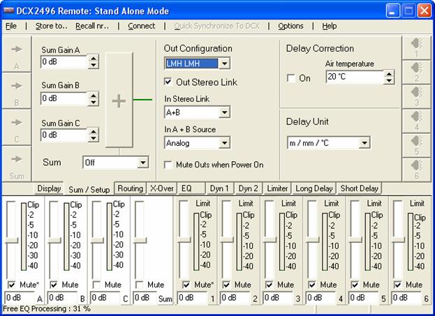
Arriba vemos la configuración LMH LMH escogida, así como todos los controles en Mute y también podemos poner la temperatura de la sala y escoger el sistema de medidas.
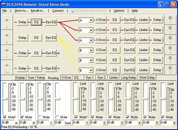
Abajo vemos como se usan las salidas 1, 2 y 3 para la entrada A y las salidas 4, 5 y 6 para la entrada B
Above, we see the LMH LMH config. as well as everything muted (we can also set room temp and measuring system (ºC/ºF, m-mm or feet-inches).
Below we can see how to use output 1,2&3 for input A and ouput 4,5&6 for input B.
For convenience, when “reading” the filter from the listening point, we choose to use input A, output 1,2&3 for the LEFT channel, and input B, output 4,5&6 for the RIGHT channel, only because we’ll see the leds lit according to our position against the speakers.
Once done, next is to find the cutoff frequency to use for each of the drivers. One solution is to read the graphs the manufacturer offers as well as the reccomended working range of the unit. This is a good starting point, but bettered by the next step, where we’ll really be able to see what’s the FR of the driver on OUR system.
Another road to choose, if no data is available, could be measuring the drivers and learn how much the FR extends, so we could have them working well within its limits avoiding i.e. to have a tweeter “squeek as a pig” ?…having chosen a way too low crossover point for it.
Later on, we’ll explain how to measure and adjust conveniently the sound offered by the active system, but to keep it going with the initial set up, the first solution will suffice by now.
Once determined the FR in wich each driver will work we need to choose the steep cutoff value, wich can be chosen in different ways:One of them is according to the FR graph offered by the manufacturer. We need to find a steep cutoff value within the limits offered.
Another would be to adjust according to the real response of the system in our room, once we have it measured, but we’ll get to it later on.A third could be to adjust according to the personal taste of each one, after listening tests.
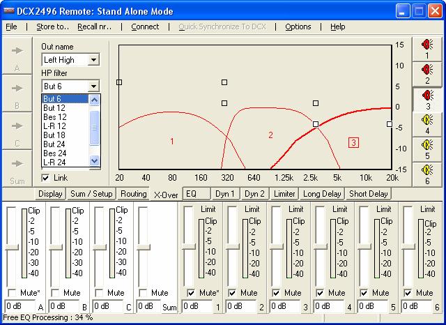
Here we can see some of the different step cutoff values that can be applied to each cutoff frequency, where the shapes of the response can be appreciated for each one:
Once we have chosen the cutoff frequencies and its steep cutoff values, we can proceed to make the system sound.
However, and still as a precaution, we’ll set the gain and volume to 0 and/or mute the crossover and the preamp, only then we’ll turn on the system.
We’ll start playing a record or CD and we’ll turn off the muting to the inputs and the outputs of the crossover and turning the volume up. We reccomend to unmute the BASS channel firstly: if we have any wrong connection, given the ability of the woofer to reproduce without further consequences any mid or high frequencies, nothing bad will happen. Then, we’ll proceed to unmute the MID and finally, if everything seems to be working fine, we’ll unmutethe HIGH.If we detect having some interconnection at fault, we’ll turn everything off and we’ll inspect and carefully study each and every connection until we find the wrong one. We insist on labelling all cables and terminals to avoid mistakes.
Once everything is OK, we’ll start listening to our new Active System. From now on, we’ll start dealing with another hard section, adjusting the system itself.
This will be the most entertaining and didactical portion, but also might be the most frustrating of all of the process of building up an active system. We are certaong that “perfect” does not exists, or at least, is extremely difficult to achieve, basically because we enter the gray area were subjectiveness plays a role: you must like what you hear out of your own system.
However, it’s needed to learn how to adjust certain parameters of the system to be able later on to decide wich sound do we like best. Regardless, we have observed over time that with just a “decent” adjustment, the results obtained are highly satisfactory.
TOOLS:
It’s very convenient (almost unavoidable) to have some extra tools to be able to make fine adjustments:
-Microphone
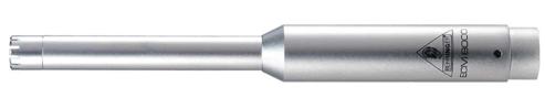
Here we can choose one of 2 options: a commercial mike or a DIY one. Both are based on an Electrect cartridge, as the well known Panasonic WM-60 AY. Just look around on the internet for the best solution within the DIY area. As a commercial solution, we chose the Behringer ECM 8000, its price (around 50eur) is great and its performance acceptable for this purpouse. We read some comments on the ‘net about this mike distorting from 100db, so to avoid this suppoused distortion, we reccomend not to use pink noise that reaches or exceeds this value, independently that 100db of SPL is loud enough for testing and surely uncomfortable to listen to for extended periods.
We’ll also need a tripod to place the mike, it’s cheap and highly versatile.
- Microphone Preamp:
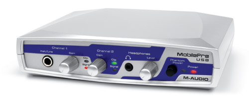
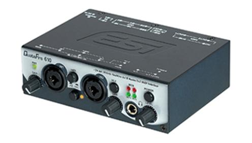
If we choose a commercial microphone, most likely it’ll need Phantom drive to work. Again, there are several DIY and commercial options. For DIY projects, there is ample information on internet, as commercial solutions, we’d go for.
M-AUDIO Mobile Pre USB
Or, the ESI Quatafire 610 (more advanced than the M-Audio, allowing sampling rates at 24 & 96 khz, featuring Firewire connection).
Any other model and maker that allows the mike to be connected to the PC is of course valid. It’ll depend on the budget we want to allocate to it. Both models mentioned are more than sufficient for what we need to. We strongly reccomend to avoid using the PC’s own soundcard. It is far more advisable to use the LINE IN or USB input than the soundcard.
With even less money but also less accuracy we can use a RadioShack SPL meter and connect it directly to the line in of our PC.
- Software:
To measure, analyze and adjust the system we need to have some program installed on our PC that will allow us to compare the sound coming from our system, captured by the microphone: some of the programs available are SmaartLive, SpectraLab V32.17 or imPulse Lite.
We will use here the Smaartlive, it’s the one we have most experience with.
- Connections:
Here we indicate the basic connections we’ll have to make for our PC and software analizes the sound of our system, captured by the mike.
We’ll take the LINE OUT of the right (or left) channel and divide it in 2 with a “Y” connector: one side of the Y goes straight to the right channel LINE INPUT, the other goes to the amplifier INPUT (this signal will be the one recovered by the mike and must be connected to the free left LINE INPUT (having chosen the right as the direct input).If our preamp has 2 inputs or outputs (usually with different connectors) we can avoid using the “Y” connection, simply connecting the Inputs and Outputs as show here below:

- Positioning:
Here we show the placement of the mike in the room to measure the system. Ideally, we’ll place it at the listening point, as if we ourselves were where the mike is, aiming it a bit upwards trying to obtain the maximum information of the room.
We can alternatively use another position, in order to measure a specific speaker or driver instead, so we’d here place the mike at 1m (39in) off the center of the driver.
However, we think the best is at the listening point, we’ll adjust then the entire system as we will hear it when listening music.
We can of course play with the positioning of the speakers and the microphone (listening point) to avoid undesired room resonances (that the mike will capture and show us on the screen).
- Adjusting levels
Once we have everything connected to our PC, the software up and running, and the system sounding, the adjustment starts. As indicated, we use the SmaartLive software, so all indications and screen captures hereafter are based on the use of this soft as well as the use of the Behringer active crossover.
On the SmaarLive soft it’ll be needed to preadjust some parameters to achieve better results when measuring. We here indicate some that were extensevely tried by some of our members that are really experts on its use:
-If you can’t see the transfer line, check that the signal is arriving at the same level on both channels, if not, use DB+/- to ecualize the graph
-Set Coh Th at least at 15% to avoid seeing absurd graphs
-Use more than 16 samples (Avg (R)) to have a stable signal without noise.
-Set FPPO on FFT Parameter
-The Mag Th works as a noise gate, the level can be seen on the “Spectrum” graph.
-If a nice looking curve is desired, set the Smooth function at 9 Pt, that is, a nicer shaped curve, but it is better to use lower values since the graph is more accurate. A value of 3 Pt will be enough.First, once all drivers are operational and emitting sound, we’d try to get a similar SPL from each driver, considering that we might have chosen to use different models with different sensitivities.
To do so, we’ll use SmaartLive’s Spectrum function, generating pink noise that will be adjusted to an adequate level: not too noisy, not too shy. If uncomfortable for long sessions, try using some ear plugs, closed protective headphones or similar. Very effective and cheap.Before adjusting levels, we need to check that the output & input levels (blue & green bars) are similar to each other. Get well up, but avoid clipping. It can be done using the level control knobs of the mike’s preamp or using the level controls of the soundcard.
Once checked the graph obtained, we’ll adjust the gain of each channel on the active crossover to get a homogeneous response from the system. It’s advisable instead of adding gain to the less sensitive drivers, to reduce gain on the more sensitive ones. A good starting point is to compare the values offered by the manufacturer, and go by the least sensitive one.
We could then obtain a graph somewhat similar to this one:
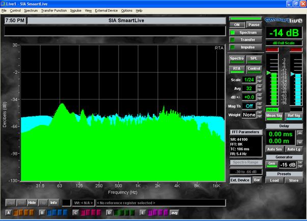
At this point, we can play with the system, shutting off drivers, changing cutoff values, modifying steep cutoff values, etc. trying to get the most adecuate driver response as described above. Don’t faint, the valleys and peaks on the graph are mainly generated by the room interaction, specially at low frequencies, while at higher frequencies, it may be caused by the driver’s own response, or the chosen cutoff frequency or both.
We can also use the Transfer function, playing with the crossover’s gain settings to get the flattest response curve.
A word about flat response: not everybody likes it, since our ears tends to be more sensitive on the mid-region, but we may chose the way we want to have it: as flat as possible or adjusted the way we best like, to each its own.
- Delay adjustments
Once the responsed has been obtained to fit our taste (whether flat or V shaped or whatever shape we like best), we proceed to adjust the delay on each driver.
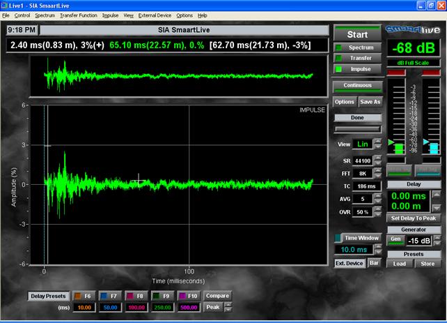
We need to use SmaartLive’s Impulse function. We’ll shut down all outputs excepting one (best to start with the LOW (woofer) output, since it’s the “slowest” one), generate pink noise and press “start”.
The woofer is the most complicated one to measure, so a small trick to do it right is to increase the cutoff frequency to the driver’s max, i.e. 700hz. Sometimes the measurements may be wrong, without coherence, and strange looking. We’ll keep measuring until we get the right one pressing “start” over and over again.Once a coherent measure is obtained, with the cursor keys UP and DOWN we’ll select a portion of the graph and with the cursor keys RIGHT and LEFT we’ll move to select just about the start of the impulse.
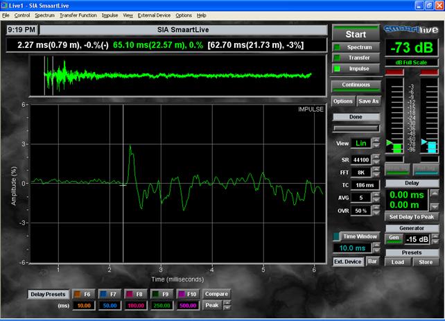
On this screen capture, we can see a coherent measure, with and without zooming:
The program, by default, will place the cursor at the max. impulse point, but we want to have it at the beggining of the impulse, right where the zero axel is cut by the curve. For enhanced viewing use the + & - keys. By using CTRL-RIGHT or CTRL-LEFT we can move the cursor along the curve, until placing it right at the start of the impulse (shown on image 2).
On the graph above, it can be seen the value in ms of the impulse, right were the cursor is situated (white line crossing the graph), we write down this value.We repeat this procedure with the other outputs of the system, writing down each of the values shown on each curve.
Once we have all the values acquired and written down, we only need to adjust the crossover to compensate those values. On this screen, we introduce the values, that are indeed nothing else but the differences in time in between the slowest (usually the woofers), the mid and the tweeters.

As we introduce the delay values on the crossover for each driver, we can check the results using the microphone by setting the Impulse function to “Continuous” and checking the new graph now generated. By doing so, we can see how the delay is modified, adjusting accordingly with the crossover until all outputs are equal.
Once the delays are equalized, we’ll go to the Transfer function and activate only the woofer output, changing the screen to Phase. We make the program calculate the delay pressing AutoSum, it’s results being (or should be) the same as before on the Impulse function. We capture the graph using the lower keys A…E + Capt.We shut down the woofers and activate the mids. We check the Phase right on the chosen crossover frequency and by using the crossover to combine the delays, phase and angle, we’ll try to match the resulting curve with the woofer’s curve (the one memorized before) trying to get a continuos curve. Of course, it will be almost impossible to get a perfectly continuos curve, but we’ll try to get it done as best as possible.
If the curves are not at the same level, we can use DB +/- to equalize it.
We repeat the procedure for phase and crossover point in between the MID and HIGH outputs.
Once reached this point, we may get a screen showing the active crossover’s program looking like this one:
Now we only need to readjust levels in between the outputs to get the sound of our liking, applying some equalization if we want to.
By using the equalizer we may eliminate some undesired peaks from the system’s response, generally caused by room resonances when interacting with the speakers. We’ll then locate those annoying peaks and we’ll apply a parametric eq centered on said peaking frequency and with a Q similar to the response graph. We’ll apply attenuation and modifying the Q value until we get to tame the peak.
Even if the peak does not dissapears completely, we can compare instantly the effects of the eq by activating and deactivating it.
However, as initially mentioned, we must try to place the speakers in the best possible spot of the room and the listening position where is least affected by room resonances.
NOTE: Should we change the positioning of the speakers or the listening position, we’ll need to readjust delays and equalization.
The number of parametric equalization that will be available to use will depend on the free capacity left over on the crossover. It may vary depending on the complexity and crossover steep points applied to our system:

After applying some EQ, we’ll be able to see the profile of our Active System on the first screen of the Behringer’s software, it may look something like this one:

To finalize, we’ll need to memorize all the crossover’s adjustments creating a new file on our PC, to avoid accidental deletions on the XO. Once done, start enjoying your new Active System!
Active XO’s systems and multiamplification are becoming more and more popular amongst users whom seek to increase their system’s qualities by a great margin.
Soon enough it’ll be common to have the entire system based on a PC as a unified source, avoiding the use of Xovers as hardware, and using only software control to do all the job, so, a good audiocard, a cable and the poweramps is all what will surround our systems. CD player, transports, dac, preamp, crossovers, everything into one single box.From here we can only encourage the use of active systems, there are numerous colleagues that are turning “active” as a mean to improve their systems, and all of them are vastly satisfied.
Of course we won’t hide its downsides, those exposed at the beginning of the article, so please weigh it in carefully before jumping to it.What might seem discouraging is the implementation costs, using several power amps could be the killer part, but we have made several tests using 6 ch A/V receivers and can only conclude that the results are great.
Some others tried out low cost professional power amps with similar results, all excellent, and recently, we have tried out D-amps: here again, same results as when using traditional AB power amps.
We hope that with this article we have broken some barriers that holded off potential users of active systems but didn’t dared to: some determination and self effort added to the usually great help that can be received from friends through forumses makes possible to install and adjust an active system, achieving glorious results.
Finally, we thank to all of our friends that made possible, through their cooperation, to bring this article to life. This article reflects some answers to many Q’s received by those of us who runs an active system.
We sincerely hope this may help to anyone curious enough to decide going for the thrill of building up an Active System.